Quick2Wire Port Expander Assembly
I finally found the time and inclination to sit down and solder together the Quick2Wire Port Expander. It was considerably easier than I thought it might be, and required only patience, careful following of the instructions and gratuitous use of blue-tac, a trick learned from the masterful Gordon Henderson.
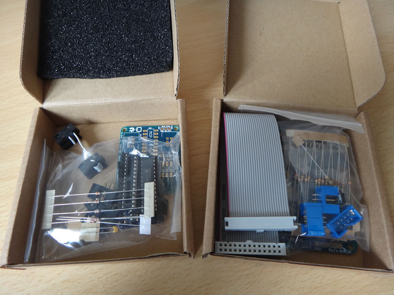
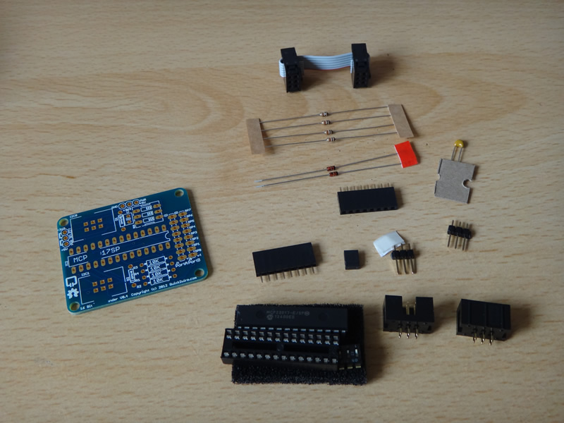
Most of the components have fairly obvious places in the Port Expander kit, but I followed the assembly guide so I'd avoid any silly mishaps like incorrectly orientated diodes or box headers.
The kit has 15 parts to solder, totalling over 80 solder joints and took me around an hour to finish.
The heart of the board is a 16-bit MCP23017 i2C parallel port expander, the same chip as found on the Raspberry Pi Port Expander Board. It offers 16 additional I/O pins which are broken out into two rows of 8 female headers suitable for male-to-male jump wire connections to a breadboard, or jump wires at a pinch.
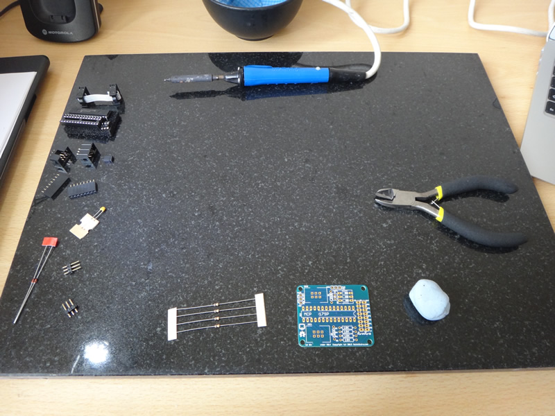
Following Gordon's tips from his ladder board assembly video I secured each part with blue-tac and finished each joint in 3-4 seconds.
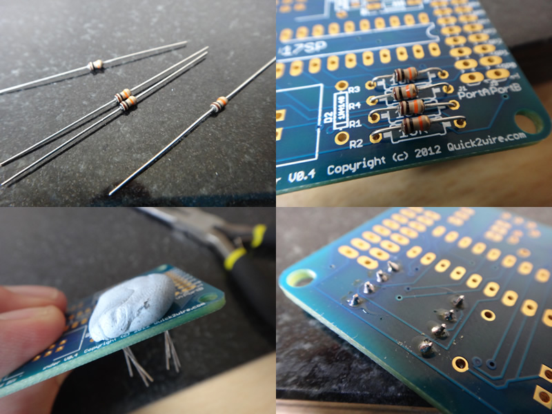
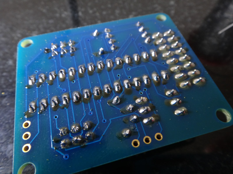
Once I'd finished soldering, I dabbed off any remaining blu-tac and inspected the finished product.
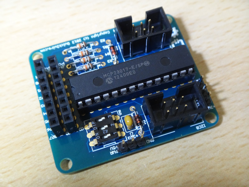
The back is the usual mess of burnt flux or PCB, but from the front it's a work of art.
I haven't been able to test the Port Expander, I've yet to solder the main board together, but the results look promising. You can buy the Port Expander on its own for under £10 or, at time of writing, grab the Port Expander Combo Kit up for £22.66. This is a little more expensive than simply grabbing the GPIO breakout board and MCP23017 expander from HobbyTronics, but the Quick2Wire board offers much more potential, a Python library and a shiny new Analogue Board.
« Back to index Posted on 2013-03-10 by Philip Howard