When I shifted into full-time employment in the Raspberry Pi ecosystem this blog got left behind and forgotten and finally succumbed to bitrot.
This version is an HTML-only archival snapshot, mostly for my own curiosity and to make these little tidbits of my Pi history findable again.
If you've found your way here, I hope you find it useful, or perhaps a little glance into the origins of some Pi projects, and me!
I mostly now write about things on my main site Gadgetoid.com by night, and write software for Pimoroni.com by day!
In my last article I introduced hobbyist veterans Parallax and their Propeller Microcontroller. The oft-overlooked multi-core gem is available in many form factors, but I got my hands on the Arduino-shield-compatible ASC+ to test.
I imagined that this article would be about C, and the new-fangled C compiler and development tools that have all but replaced Parallax’s house language, SPIN, and Parallax’s own development tools. But then I found myself intrigued by the SPIN language, and by Propeller Assembly and couldn’t help but dig deeper. So, I’ll reserve my C tinkering with blinky lights for the next article and instead walk you through my journey of discovery with SPIN. This is something of a brain dump, so apologies if it’s erratic and poorly structured, otherwise I hope you enjoy!
This article isn't going to detail how to get started, but rather an attempt to make you want to get started!
What on earth is SPIN?
SPIN has been described as a cross between Pascal/Fortran and BASIC. I’ve no experience with Pascal or Fortran, but I can detect a little of BASIC’s DNA within the language. It’s no surprise that Parallax would take this direction, given their strong association with BASIC through the BASIC stamp microcontroller. SPIN is clearly a beefed-up BASIC that I'd guess was designed to be at least somewhat familiar to their existing users, while working in a whole lot of useful syntax sugar and, of course, support for the multi-core nature of the Propeller.
SPIN is compiled into bytecode and executed by a software interpreter which is stored within the Propeller’s built-in ROM. This interpreter is copied to each cog ( core ) that needs to run SPIN. The astute should spot two potential “problems” with this setup- first and foremost, precious memory is being expended on the interpreter, and second, interpreted languages are inherently slower than their raw machine-language counterparts.
Contrary to the first point above, however, SPIN can actually be more space-efficient than Propeller Assembly. A SPIN opcode is only one byte long, with optional byte-long parameters following it. Propeller Assembly opcodes, however, are always 4 bytes long.
I put this to the test fairly unscientifically with an I2C driver available in both SPIN and PASM. The PASM driver compiled to about 1000 bytes ( 250 longs ) and the SPIN driver compiled to 612 bytes ( 153 longs ). Now these are functionally similar, but not exactly equivalent libraries, but it illustrates a point- you can, if you wish, trade performance for size.
Except that you don’t need to do this with the Propeller. The multi-core design is ingeniously architected in such a way that you can use PASM for lean bits of code you need to run quickly, and SPIN for bulky chunks of code that aren’t performance critical. Any cog ( core ) can run one or the other, and running a chunk of assembly on a cog is as simple as telling it where to look. At runtime the assembly opcodes are copied from the primary code memory into the cog you’re starting, and then executed.
Propeller Magic!
This leads me onto one of my little Propeller discoveries ( I’ve had a number of pleasant surprises playing with this Microcontroller ), which I happened upon by chance while playing with some basic Blinky examples in PASM.
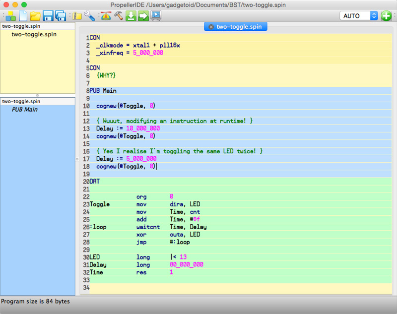
Because the assembly is copied from memory to the cog in which you want to run it, and because even data flashed to the EEPROM is copied into the Propeller main memory before you actually run it, something magical is possible. You can modify assembly opcodes at runtime before sending them to a cog.
The practical upshot of this is slightly bonkers. You could, for example, run a serial terminal monitor on one cog, accept packets of assembly code, execute them on other cogs and return the results. Now, I’ve not tried this and couldn’t think of a reason why you’d want to, other than it’s cool, but... well... it it’s cool!
My first steps with SPIN
Now it’s probably time to cut the waffle and get to the point. Working with SPIN on the Propeller requires, of course, a compiler and an IDE.
Now, there are great tools out there for the Propeller, but Parallax don’t make it particularly straightforward to find them. The ASC+ product page, which was my starting point for information about the board I’d been given to test, links only to a dry schematic ( none the less useful ) and a somewhat crusty wiki page that recommends either Brad’s Spin Tool, which was seemingly last updated in 2010 and decidedly crusty ( although perfectly functional ) or Parallax’s own Propeller SPIN Tool, which is Windows only and apparently last updated in 2010.
I downloaded both of the above, using Parallax’s own SPIN Tool quite happily on Windows, and then switching to Brad’s Spin Tool on my Mac. Both of these applications worked perfectly fine and allowed me to get a brief look at SPIN, which appeared daunting at the time, but I quickly abandoned them and switched to the C/C++ capable SimpleIDE. Until a couple of days ago...
I’d had a sudden urge to try SPIN again, and it was through a Parallax news post, of all things, that I discovered they had a recently-opened GitHub account full of juicy open-source software repositories. If you were around when Arduino first landed and was being touted as “The Basic Stamp Killer”, you’ll know that, aside from price, one of the major criticisms of Parallax’s BASIC stamp offering was the lack of open source software and, more so, the lack of anything other than Windows support. It’s taken them a long time, but Parallax are finally beginning to embrace, support and publicise the growing effort to make their products easier to use and more widespread.
I found it surprising that only the new post really drew attention to this GitHub goldmine; I’ve been involved in evaluating alternatives to the AVR at Pimoroni, and one of the biggest considerations is the availability of good tools. Parallax should be beating makers around the head with this software, waving their arms, and shouting from the rooftops about it, it’s a big deal! Okay, so it was only announced a couple of weeks ago, but when it comes to selling makers a shiny Arduino alternative, then the availability of actively maintained, multi-platform software support is second only to good documentation and support.
Parallax have nailed the latter; their forums are a vibrant and bustling hive of Propeller and BASIC Stamp veterans, all eager to share their passion for the devices. Even Parallax’s own engineers drop in from time to time, how often does Joe-maker get to talk to chip designers at Atmel?
Stumbling upon Propeller IDE
So, after much deliberation, exploration and several good barks up several wrong trees I arrive at Propeller IDE ( https://github.com/parallaxinc/PropellerIDE ). For the remainder of my Propeller articles I’ll be talking about either Propeller IDE, or the PropGCC-based Simple IDE- everything else, functional though it may be, seems outdated, unmaintained, out of fashion or poorly documented.
Propeller IDE is an open-source IDE for the Parallax propeller that’s built around OpenSPIN, an open-source compiler for the SPIN language. Unlike the, *cough*, festering sack of ungainly awful broken and horrid Java kludge that is the Arduino IDE ( I tend to use AVR GCC and any other editor ever and avoid the Arduino libraries completely ) the Propeller IDE is lean, fast and somewhat more capable.
Okay, to be fair the Arduino IDE is at somewhat of a disadvantage by comparison, having to support multiple Programmers, and multiple different architectures really holds it back. With the sum total of one single Microcontroller to support, the Propeller IDE is expected to be much more focussed, far more uncluttered and much easier to get started with.
And it really is. I love using Propeller IDE. It touts everything from uncomplicated code-compiles, to automatic detection of the serial port your Propeller is connected to. It boasts extremely fast, straight-to-memory uploads of code. It brings a tear to the eye with a one-click code-upload and serial terminal button, and leaves minds thoroughly melted with tree-view browsing of objects and methods, and auto-complete, and ... I think that’s actually everything I’ve learned about it to-date.
The only thing Propeller IDE isn’t, is aesthetically pleasing. Somewhere, at some point during the inception of the SPIN language someone decided that sections should be highlighted with garish and obnoxious background colours.
Let me just fill you in on what I mean by sections, since I glossed over that in my summary of the SPIN language. A section is a portion of the code with a very specific task and SPIN has a number of these. The CON section is where you define all your constants, the VAR section all your variables, the OBJ section all your objects, each PUB section describes a public subroutine ( you might know them as a function or method ) and each PRI section describes a private subroutine. You can also have a DAT section, where you can simply switch seamlessly into PASM and write assembly to be loaded into cogs for those time-sensitive tasks.
I love the section structure, it promotes good practises and keeps code tidy and readable. There’s also something brilliant about the background highlighting, the alternating colours make it really, really easy to visually parse code, and any two adjacent PUB, or PRI sections will have alternating shades of the same colour to make it obvious where one subroutine ends and another begins.
Unfortunately it looks horrible. Fortunately, however, PropellerIDE is open source... so tweaking these colours to a simple dark-navy-blue alternating pattern shouldn’t be too much of a struggle! I must try!
Incidentally you can also have adjacent CON sections, and these are handled with alternating shades... why in the world you’d ever want to do this is beyond me, but it’s handled gracefully if you do.
Wrapping up!
Okay, I think I’ve written quite enough for one post. The important points to remember from this wall-o-brain dump is that the Propeller is cool, the software is painless, responsive and fast, and Parallax are clearly making every effort to appeal to the maker community in order to, perhaps, make up some ground while Arduino appear to be somewhat grasping for direction and meaning ( I love Arduino, but I feel they’ve really lost the plot lately ). I found it easy enough to find the guidance I needed to get started with SPIN, even with the Parallax forums being offline for the past few days, and I feel that it’s really quite a good prospect for a maker looking to stray away from the trendy brand-name platform.
Disclaimer
Although Parallax were kind enough to supply me with an ASC+ to play with, they are neither paying nor encouraging me to extoll the virtues of their product. I use AVRs on a regular basis as part of my job at Pimoroni, but am always ready to get excited about something different- these articles serve to chronicle that excitement, and hopefully instill it in you.
Parallax are the embodiment of the classic underdog tale, and their commitment to doing things differently and keeping close to the makers and enthusiasts who made them what they are today is really what makes them special. Founded in the bedroom of Chip Gracey in response to the lack of hardware/software education opportunities, Parallax have always been a company by makers, for makers.
Although they’re no PIC or AVR, Parallax could arguably be attributed as the founder of widespread homebrew microcontroller development. As far back as 1992 they developed the BASIC Stamp, the tool that they needed to power their own hobby projects. This postage-stamp sized, affordable microcontroller gained traction quickly and created its own industry. By letting ordinary folks program microcontrollers for the first time, it gained widespread appeal among everyone from scientists and engineers to bedroom-bound hobbyists. They had shifted over 125,000 BASIC Stamps by the end of 1998 and developed a range of peripherals to support them. By 2002 this had grown to over 3 million. The BASIC Stamp was very much the Arduino of the last two decades, and in fact predated the current hobbyist go-to by over 10 years.
With the success of the BASIC Stamp giving Parallax a solid foundation, Chip turned his attention to designing the bold and unconventional Propeller Microcontroller. The Propeller, known more specifically as the P8X32A, was introduced way back in 2006 and now has a diverse array of education and maker-friendly form factors. In this article I’ll be giving you my first impressions of the Arduino-like and shield compatible Propeller ASC+.
What is the P8X32A?
The Propeller Microcontroller is a beautifully quirky detachment from what we’re normally familiar with in the world of Microcontrollers. First and foremost it’s multi-core, featuring 8 32-bit cores called “cogs”. This is a little bit like having 8 Arduinos connected together and running from the same codebase- you can instruct a cog to perform a task, and it’ll run happily in its own little world and let your main program flow continue uninterrupted.
Secondly, and somewhat more controversially, the Propeller is devoid of any purpose-specific peripherals. It doesn’t have an ADC, it doesn’t have PWM, it doesn’t have a watchdog timer, or interrupts and, surprisingly, it doesn’t even have any onboard non-volatile memory… at… all.
This may make the P8X32A sound utterly dismal, but many of these things are balanced out effortlessly by the sheer amount of processing power available on its 8 cores. You can, for example, dedicate a core ( or cog in Propeller-speak ) entirely to generating a PWM frequency, or to acting as a VGA driver, or a driver for WS2812 or SPD8806 LED strands, or to polling for certain conditions and acting as an interrupt-handler.
The P8X32A is also not as robust as you might expect a common AVR ATMega Microcontroller to be, it only supports 3.3v signals and thus requires logic level conversion to interface with 5v systems. These are pretty rare, admittedly, and many sensors and devices commonly used by hobbyists either only work at 3.3v, or are happy with it.
The P8X32A has its differences, or its quirks if you will, and these are what make it interesting. It’s most definitely not an AVR and clearly not a PIC. It is different, and new. This is exactly what drew me to the P8X32A and, as you’ll find in these first impressions and any future rantings about the Propeller, exactly what made hacking around with this new toy fun.
The Propeller can run up to a whopping 80mhz, every cog processes instructions simultaneously and they can be started and stopped on-the-fly as and when you need them. Using Propeller Spin language and the Spin interpreter you can even create self-modifying code if the fancy takes you. It’s a cool architecture, and a great challenge for someone looking to graduate from from Arduino and test their mettle with some new concepts.
What is the ASC+
First off, ASC stands for Arduino Shield Compatible. But acronyms aside, just a single glance at the layout of the board makes it pretty obvious which market it’s aimed squarely at. The ASC+ is touted as a powerful, drop-in replacement to an Arduino UNO/Leonardo and is intended to be an easy way to add some oomph to your projects without a total change of form factor.
The ASC+ takes a P8X32A and combines it with all the support peripherals required to make it behave more-or-less like an Arduino. This includes an ADC, of course, to give it 8 analog inputs and a 64KB EEPROM that gives you 32K of program space, and 32K of data storage. It’s also got an integrated Micro SD slot on the underside of the board, handy for storing logs, data files, wav files and, if I’m not mistaken ( and with the right bootloader ), even program code and, if you’re completely bonkers, additional ( but slow ) memory.
The handling of 5v signals is done by means of an inline 2.2k resistor for each Arduino shield header pin. This is an ever-so-slightly untidy solution and means you must add a solder bridge across two pads underneath each pin if you wish to use them reliably for high-speed 3.3v signals.
The combination of an interesting new Microcontroller with a familiar format is comforting and a great way to explore new possibilities with slightly more of a safety net and less of a learning curve than a bare 40-pin DIP.
So, is it hot or not?
I say hot. The Propeller is not new, and many of you may have come across it before, but it is an excellent way to start playing with something a little different. Its killer feature is true multi-core support, those 8 32-bit cores can be put to a diverse range of uses and can run a mix of assembly, spin or compiled C. In my first experiments I set it up to drive 26 WS2812 and 160 LPD8806 pixels simultaneously- the LPD8806 had a slug of inline Spin running in its own cog, the WS2812 was implemented in Assembly also running in its own cog and my glue code was written in C using Simple IDE. In my next Propeller article, I’ll tell you how I got this set up and hopefully give you some pointed for replicating my success- after that… who knows! I’ve got 3 cogs left unused and I’m eager to see how far I can push this micro.
What makes the Propeller P8X32A even hotter right now is the fact that it’s open source: https://www.parallax.com/microcontrollers/propeller-1-open-source. If you already have a sufficiently beefy FPGA board then you can fabricate your own Propeller chip and start programming and tweaking it. Parallax are working on a Propeller successor, and are clearly hoping that the feedback and improvements they see on the open-source P8X32A will be useful for refining the design of the Propeller 2. There’s nothing cooler than a hobbyist-friendly company who both listen to their customers and share their IP for the wider benefit of all- Parallax are awesome people doing awesome things and I highly recommend tinkering with their boards.
It's been a while since I reviewed anything Pi-related, or rather a while since I took the time to actually write about it rather than simply Tweeting my adventures.
I have a few bits and bobs in my pipeline, but today I thought I'd talk about a shiny metal Raspberry Pi case from a brand new designer/manufacturer apparently based in the Netherlands.
The origins of Anidées are quite hazy, however, and I can't confidently say where they're based. What I can say, however, is that they make a really nice machined-aluminium Raspberry Pi case.
The Anidées "AI-PI" case is available in both silver, with a clear acrylic top, and black with what looks to me like an extremely dark, reddish-brown acrylic top which they call black.
In the box you'll find not only the case, but an acrylic VESA 100mm mounting kit with fixings, a Micro-USB to USB cable with an inline power switch and screws for mounting the Pi securely inside.
In order to effectively use this case, you'll need a Pi with mounting holes, so if you're still rocking a dinosaur rev 1 or 1.1 then look elsewhere! I found this out the hard way, and currently have a Model A mounted inside mine. It leaves a few gaps, but it fits fine.
Anidées were kind enough to send the black version of their case my way. Black is definitely my preference, and I was pleasantly surprised since I didn't even know it was available in black. The extremely dark, but definitely not-quite-black lid is what I find most endearing. It has a colour very much reminiscent of the glass I remember from 1980s Hi-Fi cabinets, perhaps I'm imagining it, but I always remember a dark, chocolate brown.
The acrylic lid comes with extremely obvious paper stickers covering it for protection. Unlike the Pibow, where the clear layers are rather infamously and frustratingly confused with opaque plastic, it's absolutely clear that these should be peeled off.
The case itself is an impressive hunk of metal, it has cut-outs for all the usual ports and includes handy clip-in plastic blanking plates for the RCA and 3.5mm jack connections which are commonly unused. It doesn't protect a full-sized SD card, however, leaving it protruding slightly. I feel a little extra length could mitigate this somewhat and render the SD slot safe from the sort of accidents to which it seems prone. Forget using a half-height adaptor, since you'll not be able to remove and re-insert the SD card without completely removing the Pi from the case.
The Pi is screwed in securely with two metal screws and, once the acrylic top is secured into position, is extremely well protected. If you opted for a half-height SD card and didn't need to remove/reinsert it often then you're going to have more Pi-protection than you'll ever need.
The acrylic top is thick ( a generous 5mm ), solid and extremely good quality. It's difficult to tell if it's been cut with a physical tool or by a laser but I'd guess the latter. The edges are smooth and don't have any burr, and the screw holes are counter-sunk for a flush top. It's a small but worthwhile touch that makes all the difference.
While the top doesn't have any holes for IO, the case itself has a cut-out for fitting a GPIO cable that you can run to a suitable breakout board ( like the Pi T cobbler or otherwise ). The inside of the case is spacious enough to fit a PiGlow, and the black/brown top will reduce the LEDs to levels you can view without vapourising your eyeballs.
I'll admit that I haven't tried the VESA mount yet. I don't have anything with 100mm VESA mounting holes on the back, and even if I did I can't quite concieve why anyone would want to hide a case as beautifully machined as this behind a TV or LCD display.
The USB cable with its inline power switch is extremely useful, It's a handy thing to have around but very similar things can be picked up cheaply online. It's a good value-added extra, and makes the AI-PI case into what I'd consider a really nice gift set for the discerning Pi-owner.
In terms of price, it weighs in at a hefty £39.99. That places it near the top of Pi-case pricing. In fact it's right alongside the UniPi Aluminium Raspberry Pi Case which has fewer accessories but does come with a handy cut-out top for GPIO and camera access. In context, this makes the AI-PI a pretty good deal for what it is. It's an appropriate price for a machined aluminium case. If you want to mix-n-match you can also buy a replacement top cover for a fiver, letting you have a black case with a clear top, or a silver case with a black top.
In summary, this is a really slick case. It's beautifully packed in a very giftable box, and comes with some handy accessories that set it apart from its closest competitors. It's not, as first glance might suggest, overpriced. It would, however, be great to have a alternate top with GPIO and Camera cut-outs.
I've got some great news, and a little update incoming to let you know why this blog has been, frankly, neglected for so long. It's for a good reason, honest! Watch this space.
I've been busy with all manner of things, from creating the Pibrella library, to helping out various folks in the world of Pi. All this has meant some rather big and exciting changes coming up, and will also mean that the tone of this blog will become rather more personal. Tutorials, guides and cool projects will be found elsewhere!
However, because old habits die hard, I will continue to post reviews of cool boards and hardware that I come across!
Some time ago I talked about the Papilio Pro. This amazing FPGA-based board is still one of my favourite and least understood boards. The reconfigurable "fabric" of an FPGA can be moulded, by means of a hardware description language, into almost any digital hardware you can concieve. This makes the Papilio Pro capable of replicating a Pacman Arcade Board, or even a powerful 32bit Arduino-compatible the ZPUino,
Brilliant though it was, where the Papilio Pro failed was in making this technology approachable by mere mortals. The Papilio DUO aims to change this.
By far its key selling point is the drag-and-drop software that GadgetFactory are working on to allow you to "draw" your circuits with basic components and then have all the HDL taken care of by the software.
Basically, you draw it, compile it, flash it and the FPGA reconfigures its internal structure to match your design. As mind-blowing as it may seem, this gives you the ability to rapidly put together real hardware components to back up your Arduino sketches.
The idea is that the DUO provides a "circuit lab", limitless opportunity to explore, debug, tweak and tinker with real digital hardware that you've created with the enhanced Arduino IDE. Features like the built-in, drop-in Logic Probe ( equivilent to an OpenBench Logic Sniffer ) make it much easier to debug the results, and incidentally make it easy to use the DUO as a logic probe in its own right.
The Papilio DUO is currently on Kickstarter, and almost certainly destined to be funded. If you want to start drawing your own hardware and talking to it from an ATmega, then get on over and grab one: Papilio DUO kickstarter campaign.

Warning!
Google Coder currently changes the password of the "pi" user account to the one you enter in the web interface. If you find yourself unable to SSH or otherwise log into your Pi after following this guide, then use the password you specified for Coder and change it back with "passwd" at the command prompt.
To disable this password change, please do this in the coder/coder-base directory before running Coder:
echo "" > sudo_scripts/setpipass
If you want to set up Coder on a non-Pi linux system, you will also need to do the above. Coder doesn't appear to use the Pi account for anything, but sets it presumably for convinience in full SD-card based installs.
And now, on with the show:
You've probably heard of Google Coder, it's being pitched as a simple way to make web stuff on the Raspberry Pi. And it is! The side-by-side code and preview is great, and the clean, simple web-based IDE keeps out of your way and lets you get down to learning.
Getting Coder up and running on the Pi can be very simple, but you have to swap to a different SD card or sacrifice your existing installation to use Google's image. That's a bit of a pain if you're just interested in giving it a try, or want to test the water before you start re-imaging an SD card!
Fortunately, the quick and easy way is not the only way. Coder is just a NodeJS application, and you can get it from GitHub here: https://github.com/googlecreativelab/coder and have it up and running on your Pi or your desktop in a few minutes!
The part of Coder you're interested in is coder-base. Here you will find server.js which you can run with Node.
Running on your desktop
To get it running on your desktop PC you'll need to download NodeJS and install it. I'll be working on a Mac, so you'll have to fire up "Terminal" ( search for it in Spotlight ) to continue once you've got NodeJS installed.
First up, let's get the GitHub repository. If you've got Git set up on your system you can just:
git clone https://github.com/googlecreativelab/coder
Otherwise, you can download Google Coder in a zip file
Unzip the file, and locate it in your Terminal session. You'll need to cd into coder-base and get some dependencies installed.
cd coder-base
npm install
You'll see npm run through a whole list of packages which it'll install to support Coder. Once it's done, turn your attention to config.js.
I changed mine to:
exports.listenIP = '127.0.0.1';
exports.listenPort = '8081';
exports.httpListenPort = '8080';
exports.cacheApps = true;
exports.httpVisiblePort = '8080';
exports.httpsVisiblePort = '8081';
You can ignore the stuff about SSL.
Once the settings are changed, fire up the server by typing:
node server.js
If all went well, you should see a message a bout generating a 2048 bit RSA key. Be patient!
Fire up Google Chrome and enter: https://127.0.0.1:8081
You'll see a warning about SSL, just continue!
Enjoy!
Running on your Pi
I'm going to assume you've got Raspbian. You should be able to follow these steps:
sudo apt-get install nodejs npm git
git clone https://github.com/googlecreativelab/coder
cd coder/coder-base/
npm install
The last step will take some time. Once npm has done its thing you need to edit config.js in your editor of choice. On the Pi you'll want to leave the IP setting as-is, but change those ports if you don't want them to conflict with an existing web server or service on your Pi. I changed mine to 8151 and 8150 respectively.
Finally, type:
nodejs server.js
You'll see a message about generating a 2048 bit RSA private key. Be patient.
Once it's done, open up Chrome and enter: https://:8151/
You'll see a warning about SSL, just continue!
Set yourself up a password, and enjoy!
If you haven't read my guide to assembling your very own ultra-minimalist Breadboard Arduino specifically for your Raspberry Pi, or created your own variant, then you should give it a whirl. The Pico PiDuino is the cheapest way to dip your toes into Arduino-compatible tinkering on your Pi, and needs nothing more than your Pi and a few jump leads to program and talk to it.
Once again, I recommend this kit from Phenoptix which, if you're in the UK, will cost you £5 and not a penny more. It's what I built my Pico PiDuino with, and it's what inspired this series of tutorials in the first place!
What's covered in this article
This article will cover installing Gordon Henderson's modified AVRdude, which you'll need to flash compiled programs to your Pico PiDuino. If you're feeling brave or using a Beaglebone Black then you can also compile a modified AVRdude from source which includes a Linux SPI programming mode, and a customisable reset pin ( https://github.com/kcuzner/avrdude ).
I will also cover talking to your Pi over Serial, using jump-leads to the Pi's TX/RX. Gordon has a great little setup script to get Serial up and running, and a config file for Minicom, too. I'll also tell you how to set up your /dev/ttyAMA0 to accept echoed strings and transmit them to your PiDuino- this is easy to use in many situations, and means you don't need to worry about a Python or Ruby library just yet (I'll cover using those in a future article).
Once communication is set up, we'll look at using Arduino-mk and the Arduino IDE. I'll be focussing on writing, flashing and compiling code from the command-line using makefiles because the Arduino IDE can be a little sluggish on the Pi, and even more so if you're running headless and trying to use X forwarding. Don't worry, it's easier than it sounds.
A word on vi/vim, the text editor
I tend to use vim to edit files. Most other guides refer you to nano, but I don't use it. To install vim ( VI iMproved ) use: sudo apt-get install vim
Once installed, you can use vim to edit text files, but you'll have to get your head around the Arcane commands used in the editor first.
To go into insert mode, press "i" - you can now type content into your file. There are other ways to go into insert mode, with varying effects, for example "o" will insert a new line.
Also useful to know is that hitting "u" will undo.
If any of these commands result in text appearing in your file, you need to exit edit mode and try again.
To exit insert mode, press "esc"
To save and quit, type ":wq" ( write and quit ) when you're not in edit mode
To quit without saving, type ":q"
Installing AVRdude
The first step is to install AVRdude. AVRdude is the application which will talk to your ATmega and flash your compiled programs to it. I touched upon this in my previous article, so skip ahead if you need to.
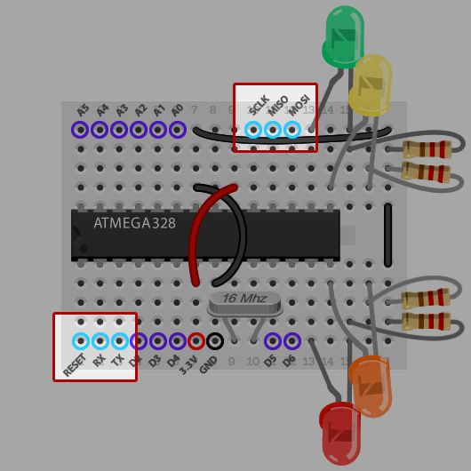
Before starting, make sure your Pico PiDuino is connected properly, you'll need male-to-female jump wires for Reset, MOSI, MISO and CLK. Make sure your power is connected too! For help, check out the Connection Overlay on my assembly microsite and the relevant pins on my Pinout Microsite.
On Raspbian you can install Gordon's AVRdude using the following commands:
cd /tmp
wget https://project-downloads.drogon.net/gertboard/avrdude_5.10-4_armhf.deb
sudo dpkg -i avrdude_5.10-4_armhf.deb
sudo chmod 4755 /usr/bin/avrdude
Once done, cross your fingers and verify connectivity with:
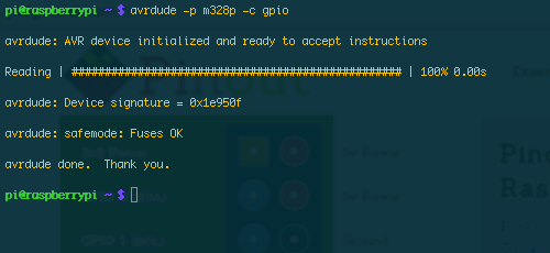
avrdude -p m328p -c gpio
Assuming everything is good, and you get a positive response from avrdude which should look something like the below, we can move on to programming.
Programming your Pico PiDuino
Now we're getting to the fun part; making your Pico PiDuino do something meaningful. If you've got 4 LEDs connected as described in my first article this means putting together a simple program to turn them on and off via Serial using the QWER and ASDF keys on your keyboard. It sounds dull, and in the grand scheme of things it is quite dull, but the basics of toggling outputs on your Microcontroller, and responding to Serial commands will help you build more interesting Pico PiDuino projects and work with more exciting hardware.
First thing's first, you need the Arduino IDE and the command-line Arduino Makefile helper installed on your Pi:
sudo apt-get install arduino arduino-mk
Next, make yourself a directory to work in:
mkdir ~/piduino
cd ~/piduino
And create a makefile by saving the following into file entitled "Makefile"
ARDUINO_DIR = /usr/share/arduino
BOARD_TAG = uno
ARDUINO_PORT = /dev/ttyAMA0
ARDUINO_LIBS =
include /usr/share/arduino/Arduino.mk
Now you're going to need something to compile. Although we're working from the command-line, we're still working with the same language you would use in the Arduino IDE; so all the tutorials are applicable. Remember, however, that we don't have an LED connected to Pin 13, but 7, 8, 9 and 10, so adjust any examples you use accordingly.

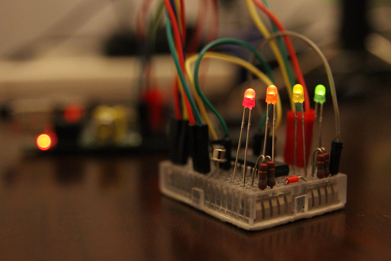
I've put together this simple variation on Blink which turns on each LED in sequence, and then turns them all off at once. If you're new to Arduino, the below code will introduce you to a few basic concepts. If you're not, just skip to the code!
Arduino basics
The "#define LED_RED 7" allows you to define an unchanging value, which you can reference later. This is useful for assigning friendly names to obscure things like Pin assignments. So we create one constant for each pin.
The "void setup()" function is run when the ATmega first starts up, and is used for setup. "void loop()" is run as fast as the ATmega can run it, and it's where we put things that need to happen repeatedly.
pinMode sets the mode of a pin, pins can be either outputs or inputs- we want OUTPUTs to drive the LEDs and so they're all set as such.
digitalWrite writes a digital value ( either 1, or 0 a.k.a. HIGH or LOW ) to a pin. 1/HIGH means an LED will turn on, and 0/LOW means it will turn off.
delay does just that, delaying the ATmega for a given number of milliseconds.
The code
Save this as “blink.ino” ( or wget https://pi.gadgetoid.com/piduino/blink.ino ) in your piduino folder alongside the Makefile. To compile it, you simply type “make” and wait… and wait. Compiling on the Pi takes a while, even for the simplest of Sketches; I'll have to look into omitting some of the unnecessary libraries.
#define LED_RED 7
#define LED_ORANGE 8
#define LED_YELLOW 9
#define LED_GREEN 10

void setup(){
	Serial.begin(9600);

	//Set all the pins we need to output pins
	pinMode(LED_RED,    OUTPUT);
	pinMode(LED_ORANGE, OUTPUT);
	pinMode(LED_YELLOW, OUTPUT);
	pinMode(LED_GREEN,  OUTPUT);
}

void loop (){
	digitalWrite(LED_RED,    HIGH);
	delay(100);
	digitalWrite(LED_ORANGE, HIGH);
	delay(100);
	digitalWrite(LED_YELLOW, HIGH);
	delay(100);
	digitalWrite(LED_GREEN,  HIGH);
	delay(100);

	digitalWrite(LED_RED,    LOW);
	digitalWrite(LED_ORANGE, LOW);
	digitalWrite(LED_YELLOW, LOW);
	digitalWrite(LED_GREEN,  LOW);

	delay(100);
}
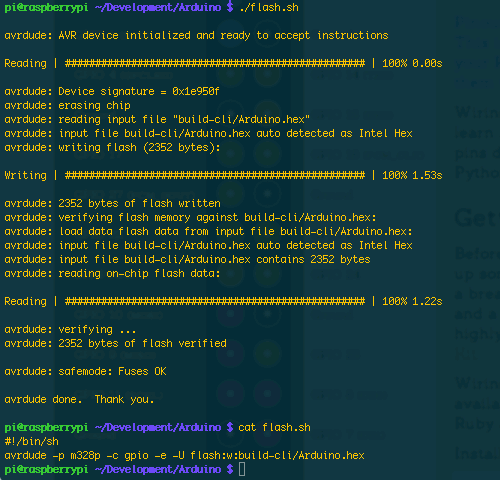
Once compiled, flash with:
avrdude -p m328p -c gpio -e -U flash:w:build-cli/Arduino.hex
I like to put this into a flash.sh file, so flashing is as simple as “./flash.sh”
Note: I've discovered that the .hex file wont always be named "Arduino/hex", use the code below to create your flash.sh to make it easy/generic:
#!/bin/sh
cat build-cli/*.hex > flashme.hex
avrdude -p m328p -c gpio -e -U flash:w:flashme.hex
The result of your flash should look something like this:
Making the ATmega blink a few LEDs is a good learning example, but it's not really useful and doesn't exploit the fact that a 3.3v powered PiDuino can talk directly to your Raspberry Pi over serial. Let's whip up a more complicated example that accepts single-character commands over serial and acts upon them. I'll do the first command - on with q and off with a - and you can try and finish off the code with the rest. Amend your blink.ino file to:
#define LED_RED 7
#define LED_ORANGE 8
#define LED_YELLOW 9
#define LED_GREEN 10

boolean heartbeat = true;

void setup(){
	Serial.begin(9600);

	pinMode(LED_RED,    OUTPUT);
	pinMode(LED_ORANGE, OUTPUT);
	pinMode(LED_YELLOW, OUTPUT);
	pinMode(LED_GREEN,  OUTPUT);
}

void loop (){
	if( heartbeat ){
		digitalWrite(7,HIGH);
		delay(250);
		digitalWrite(7,LOW);
		delay(250);
	}

	if (Serial.available()) {
		heartbeat = false;
		char ser = Serial.read();
		switch (ser) {
			case 'q':
				digitalWrite(LED_Q, HIGH);
				Serial.println("LED 3 ON");
				break;
			case 'a':
				digitalWrite(LED_Q, LOW);
				Serial.println("LED 3 OFF");
				break;
		}
		delay(250);
	}
}
And then “make clean && make” to recompile your sketch before using your flash.sh to flash, or running “avrdude -p m328p -c gpio -e -U flash:w:build-cli/Arduino.hex”
Talking to your Pico PiDuino over serial
Once you’ve got this sketch uploaded, you should notice the Red LED blinking rapidly. I put this “Heartbeat” into the code so you could tell it had flashed successfully. Once the ATmega recieves a command the Heartbeat will stop and you should be able to toggle the LED manually with “q” for on and “a” for off.
You can do this either with Minicom or by echoing these letters to /dev/ttyAMA0 after some setup.
Setting up Minicom
Once again we refer to the almighty Gordon for Minicom setup.
As per his instructions, first you should install Minicom
sudo apt-get install minicom
Then go into the minicom config dir:
cd /etc/minicom
And create a new config file:
sudo vi minirc.ama0
And paste in the settings ( don't forget to press "i" first if you're using vi/vim ):
pu port             /dev/ttyAMA0
pu baudrate         9600
pu bits             8
pu parity           N
pu stopbits         1
pu minit
pu mreset
pu rtscts           No
Once set up, simply type:
minicom ama0
And you'll be greeted with a terminal. Now you should be able to press "q" to turn the Red LED on, and "a" to turn it off again.
Using /dev/ttyAMA0
Minicom does the trick, but what if you want to send a string of commands and have your Piduino intepret them one at a time?
You can do this with a simple one-liner:
stty -F /dev/ttyAMA0 speed 9600 cs8 -cstopb -parenb
Then you can just:
echo "qaqaqaqa" > /dev/ttyAMA0
Which should turn the Red LED on and then off again 4 times.
Stay Tuned!
I've had success programming a Pico PiDuino with the BeagleBone Black, although the setup is a little trickier, it requires Ubuntu for starters, and the pinout is a little confusing due to the Bone's many, many GPIO pins. Still, I have a guide in the works for Beaglebone Black users, so stay tuned!
I have a couple of ideas in mind for the next article in the series. Let me know via Twitter @gadgetoid which you prefer. Either committing the Pico PiDuino to perfboard, or getting some more exciting components connected.
Useful Links
There's little doubt that you've at least heard of Arduino if you're interested in hacking around with hardware on the Raspberry Pi.
Arduino have brought a whole variety of Atmel-based boards to the market, coupled with the easy to use Arduino IDE, in an effort to let hardware hackers, hobbyists and professional prototypers easily get up and running with Microprocessor development. Unfortunately, the official Arduino boards can be a little pricy if you're just wanting to dip your toes into the Arduino/Microprocess programming water.
The good news is that all you really need is an Atmel ATmega processor, a handful of components and a Raspberry Pi. You can pick all this up ( apart from the Pi ) for little over a fiver.
I should probably start with a disclaimer; the Arduino-compatible we're going to build in this tutorial is absolutely, totally, irresponsibly barebones. In a proper breadboard Arduino build you should have a host of capacitors to decouple your power supply, and probably at least some protection circuitry between it and your Pi. If you're at all concerned about blowing up your Pi, read no further!
Introducing the Pico PiDuino
This is the first in a series of guides detailing how to build and program an ATmega 328-based Arduino-compatible microcontroller using only your Raspberry Pi.
First, I'll will walk you through obtaining the parts and assembling what I will refer to henceforth as the Pico PiDuino.
The next guide in this series will teach you how to program it, and then talk to it over serial from the Pi.
The Pico PiDuino is a barebones Arduino-compatible, that means it works with the Arduino IDE and uses the Arduino bootloader. It's designed specifically to be connected to, and powered by the Pi - but you can program it with a USB-to-Serial breakout or power it standalone with a handful of batteries or even, with the right components, a mains adaptor.
Why learn to program an ATmega/Arduino?
Because of their flexibility and robustness, being able to program a microcontroller is a useful and rewarding skill to have, and it's fortunate that it's possible to leverage your Pi to get started quickly and cheaply with a trusty ATmega 328.
- Learning to program an ATmega, or Arduino, will allow you to build much more specialist control systems which use less power, are much less complex, less prone to failure and more robust than the Pi. These are great for things that the Pi isn't necessary for.
- Once you've grasped the basics and have a project in mind, you can even move on to playing with some of the brilliant official Arduino boards and all the programming skills you pick up will translate right over.
- If you're wanting to produce your own product for sale, you can build your own hardware around an Arduino-compatible ATmega, program your software in the IDE and ship a finished design supporting an ATmega 328p or similar microprocessor.
- It's a fun challenge for a weekend.
The bill of materials
If you're still with me, then I'm going to assume you've got a reckless and irresponsible streak and want to hook an ATmega directly to your Pi and get started as fast and cheap as possible. Enough introduction; Let's get started!
You will need:
- One ATmega 328p Microproccessor, in a 28-pin, breadboard-friendly package
- One 16Mhz Crystal Oscillator
- 4 LEDs, it doesn't matter what colour but Red, Orange, Yellow and Green look nice together
- 4 resistors for your LEDs, about 220 Ohm or higher
- 8 female-to-male jump wires for connecting your Pi to the Breadboard Arduino-compatible
- 4 male-to-male jump wires for wiring up the Breadboard Arduino-compatible ( or 3 jump wires and a 0Ohm resistor )
- And to build it on: One 170 point breadboard, the really, really tiny one
To avoid confusion, I recommend using Red and Black wires for your Live and Ground connections and picking 8 other distinct colours, if you can, for the other connections. Connecting leads in the wrong place can have "undesired" results. To be extra-safe you should always shut down your Pi before connecting jump leads, but I'll let you in on a secret; I don't!
The best way to get most of the parts you need is the fantastically good value "Bare Bones" £5 Arduino Kit from Phenoptix. In fact that's the very kit I'm working with. It also comes with a host of protective capacitors, a reset switch and some other components for a stand-alone Arduino that you wont need for this tutorial. If you don't have jump wires then you can also pick up a pack of M/F jump wires, far more than you'll need! If you go for this kit, you'll also need to dig up 3 more LEDs ( or 4 of any type ) and 3 or 4 resistors to go with them.
Putting it together
What we're effectively building is an even more minimal version of the "Shrimp" variety of Arduino-compatible, with 4 LEDs for you to experiment with. We won't be using capacitors on the crystal (unless you feel you need to), or the reset capacitor or pull-up resistor; it's quicker and easier to omit these until you need to use your mini Arduino for something other than tinkering. In my experience, my Pi didn't agree with having a pull-up resistor on the reset line and trashed its SD card twice; this hasn't happened since I removed it. It could be coincidence, but I'm not taking any chances.
To make things really easy, I've built a micro-site which will walk you through the build process. Find it here: https://pi.gadgetoid.com/piduino/pico-piduino
We'll be aligning the ATmega to the left of the breadboard and using the space at the other end to squeeze in the LEDs.
- Orientate your Breadboard so that the number 1 ( numbers should be visible faintly on the edge ) is at the bottom left
- Place your ATmega with the little notch facing left, and aligned against the left edge of the Breadboard
- Make sure the ATmega pins line up with the holes on the breadboard, and push it firmly in with even pressure.
- Locate column 9 and 10 on the bottom edge ( with the notch facing left ), and bridge them with the Crystal Oscillator. If you can't see numbers, count the holes.
- Grab one male to male jump wire, preferably a red one, and bridge column 7 on the bottom edge to column 9 on the top edge
- Grab another male to male jump wire, preferably a black one, and bridge column 8 on the bottom edge to column 7 on the top edge
- Grab the next jump wire, or an 0 Ohm resistor, and connect the lower column 17 to the upper one, creating a mini Ground rail for your LEDs
- Grab your last jump wire and bridge the top of column 17 to the top of column 7 to ground your LEDs Ground rail
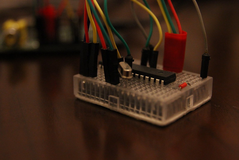
You now have a working ATmega on a breadboard. Yes, it's that simple to get started! If you're confident getting it hooked up you can now visit my Pico Piduino assembly micro-site and click "Connection Overlay" to see where things should connect.
Cross reference this with my Piout Microsite to see which pins on the Pi are the ones you need to connect it to.
To verify that your ATmega is set up correctly and can be programmed, you need to set up the programming connections which are as follows:
Finally, connect the end of column 7 on your Pico PiDuino to your Pi 3.3v Pin, I recommend using pin 17 and the end of column 8 to the Ground on your Pi. I use pin 25 at the bottom right. This should keep all your connections in one tidy block.
Testing your Pico PiDuino
First you'll need to install Gordon's modified Avrdude on Raspbian, that means doing the following:
cd /tmp
wget https://project-downloads.drogon.net/gertboard/avrdude_5.10-4_armhf.deb
sudo dpkg -i avrdude_5.10-4_armhf.deb
sudo chmod 4755 /usr/bin/avrdude
Once installed, you can check your Pico PiDuino is set up and connected correctly using:
avrdude -p m328p -c gpio
If everything is working fine you should see something like: "avrdude: AVR device initialized and ready to accept instructions" If so, well done! Let's add some LEDs.
If not, double check your connections. It should help to follow my assembly guide and use the Connection Overlay.
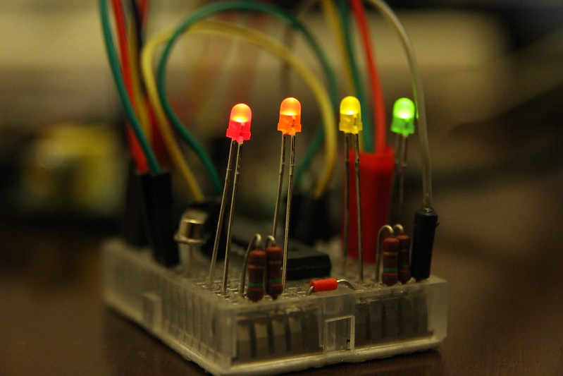
Adding the LEDs
If you haven't already jumped the gun, you'll notice that I didn't connect the LEDs above. It helps to do things in phases, and once we've got a working ATmega up and running it makes sense to test it.
The LEDs are cleverly clustered around the Arduino digital pins 7, 8, 9 and 10. These are good for a number of reasons:
- They're right at the end of the ATmega
- They're in sequence
- They don't conflict with any of the programming functionality
Most normal Arduino builds assume pin 13 is an LED, so if you use any demos from the Arduino website, or for any other Arduino-compatible devices make sure you update the LED pin to 7, 8, 9 or 10.
Connect the LEDs and resistors as follows:
- Put the long leg of the Red LED into column 13 at the very bottom, and the short leg into column 15
- Put the long leg of the Orange LED into column 14 right up against the ATmega, and the short leg into column 16
- Put the long leg of the Yellow LED into column 14 on the top half of the breadboard, again right up against the ATmega, and the short leg into column 16
- Put the long leg of the Green LED into column 13 at the very top of the breadboard, and the short leg into column 15
By now you should have 4 LEDs connected in two pairs, with two rows gap between them. Place a resistor in each of these 4 rows, bridging the short leg of each LED to the Ground rail.
We're done. Make sure everything is connected properly and fire up avrdude for one last test:
avrdude -p m328p -c gpio
Successful? Well, I'm afraid this article is getting a little long and I'll have to end here. Stay tuned for the next in the series when we will learn how to program your ATmega-powered Pico PiDuino from the command-line.
Useful links
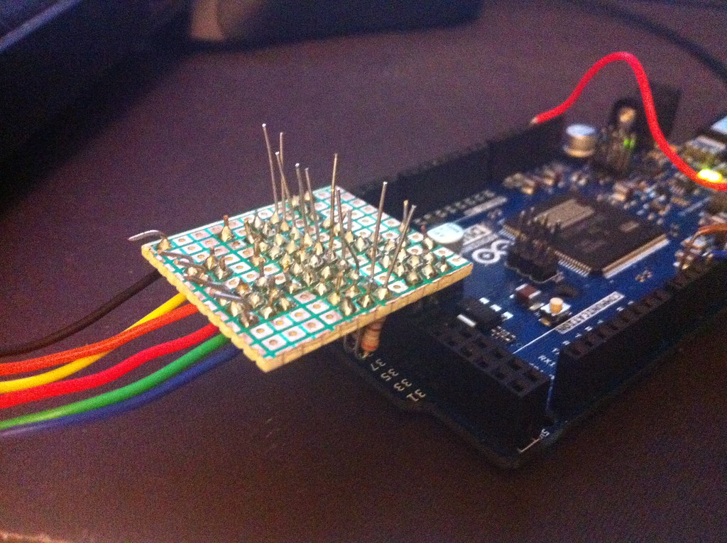
One of the first things that excited me about the Arduino Due was the possibility of VGA output with nothing more than a few resistors, a VGA connector and a bundle of wires. Arduino Forum member Stimmer has produced a brilliantly fast and low level VGA library that gives 8-bit colour at 320x240 pixels. Plenty of output for basic games, graphics demos and other visual tinkering. You can get this library here: https://stimmer.github.io/DueVGA/
Getting Connected
VGA is fairly simple in the hardware department, requiring an array of 10 resistors which form two pairs of 3 ( 3 bits red, and 3 bits green ) and one pair of two ( 2 bits blue ) plus two for the horizontal and vertical sync signals. I found that the hardest part of building out an adaptor was finding the right resistor values, but a little trial and error on a breadboard and a seeming inability to discern between red and orange finally lead me to a working prototype.
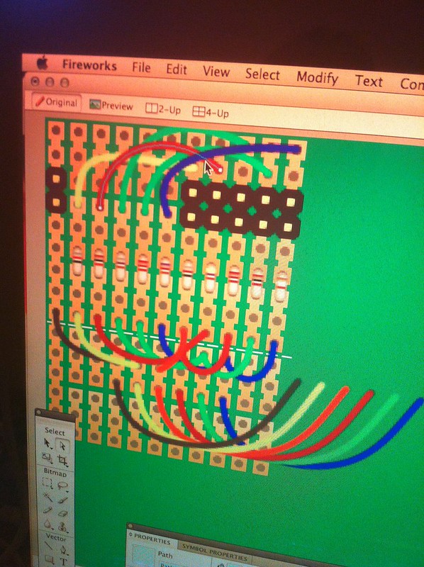
The next step was translating that prototype to perfboard. I used a small piece of 3-hole breadboard from Clas Ohlson. I used Fireworks to manually sketch out my design beforehand and compress it down to a cozy 11 tracks wide.
10 of these tracks were broken into sets of 3 holes, and the 11th was continuous and used to join the ground on the Arduino Due to the ground on the VGA connector.
I stood the resistors upright to save room, and managed to pack them into a perfect row of 10 with some spaghetti wiring joining them together. The downside of this design is that it overlaps a number of unused inputs on the Arduino Due. Fortunately I was able to tuck the wires for my MegaDrive controller port underneath my PCB and make use of these otherwise lost and forgotten inputs, so everything ended up very neat and tidy.
Once set up and running, and after remembering to trim the leads off the resistors so they didn't intefere with each other, the picture was perfect. This is the first thing I've ever committed to perfboard, and I'm more than happy with the result.
Converting Bitmaps
After setting up DueVGA and assembling my adaptor, the next step was to do something interesting with my new-found VGA-output functionality. Many DueVGA users, including Stimmer, had concerned themselves with drawing fractal patterns which, although cool, didn't really interest me. I decided to ressurect some old tricks I used with Monochrome graphic LCDs on the ATMega328 and create a bitmap converter.
The 8-bit output of DueVGA uses a number between 0 and 255 to represent a colour. The first three bits of this number represent Red, the second three Green and the last two Blue. In practise the bias toward Red and Green doesn't result in poor image reproduction, but having only a handful of possible blue values is an odd concept to grasp.
My challenge was to map these 256 colours to their equivilent RGB/HEX colour codes and produce a palette file which allowed PNGs to be exported from Fireworks into a format suitable for crunching down for the Due.
To do this I started with the 256 colour pallete from Wikipedia: https://en.wikipedia.org/wiki/File:256colour.png. This gave me a list of all possible colour values which the DueVGA could theoretically produce. Some amount of muddling was required to figure out which colour on this palette corresponded to which colour index on DueVGA. If you look at my Due VGA Colour Table you'll see why. Rather than the colours running sequentially from left to right and looping underneath, the palette was separated into blocks of 32 colours with the value of Blue running from left to right and the value of Green running from top to bottom. Each block of 32 colours represented an increase in the value of Red- so this resulted in 8 (Red) blocks of 4 (Blue) by 8 (Green) colour.
To avoid tripping over colours in future, I used a Ruby script to produce my Due VGA Colour Table. This shows the 8-bit hex notation for each colour from 0x00 to 0xFF and makes it easy to pluck a colour out if you need to use it directly in your code. On mouseover, it also shows the binary value and the 24-bit hex colour you're probably more likely to recognise from desktop graphics applications. If you're putting together some bitmap graphics for your DueVGA project then you can use these colours in your graphics package of choice.
Alternatively, if your graphics package supports .act colour palettes then you can load up this 8bit-truecolor-palette.act file. This is excellent for compressing and dithering more complex images for display on the Arduino VGA, and I've had pretty stunning results with a range of photos.
The final step in converting a bitmap is to take your exported, palettized PNG file and, with the help of Ruby and the Chunky PNG ( which is free from the dependency hell of Image Magick ), crunch it into a "static unsigned char" array of 8-bit colour values. For this you can use Convert.rb from my Arduino DueVGA Tools repo on GitHub.
Indexed Palettes And Byte Packing
If you're not using the full 256 colour palette for your image, I've also added index-palette support into Convert.rb which will give you a palette of 15 colours with the 16th reserved for transparency. This allows twice as many pixels to be packed into the same number of bytes, halving the size of your data. If you can get to grips with Convert.rb you'll also find it stores 3 bytes of metadata in each image containing the Width, Height and Frame Count. I use these values in my code to animate 16-colour sprites and by not hard-coding these values I can use a generic function for various different sizes of sprite. See DueVGABitmap.ino for an example of this in action!
Getting Technical
Another little trinket in my DueVGA Tools library is my HSV ( Hue, Saturation, Value ) colour to 8-bit colour convertion function. Stimmer may implement this directly in the DueVGA library. It provides a very clean and simple way of transitioning between colours ( by just incrementing the Hue value ) and is a mostly integer-implemented spin on the standard HSV-to-RGB functions you may have encountered before in Arduino LED lighting projects.
Where the DueVGA HSV to RGB differs is in the weighting of the final colour values and their packing into a single byte representing a colour that DueVGA can display.
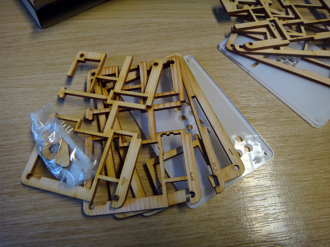
Continuing on from the PiGlow, I got my hands on another piece of Pimoroni goodness; the PiBow Timber.
I picked up a plastic PiBow for my first Pi months and months ago. It has remained my favourite and, in fact, only Pi case since that day. Many Pi cases have come since, but none have matched the elegance and ruggedness of the ingeniously engineered PiBow.
The multi-layered design of the PiBow is, when put together, extremely strong and rigid, although the individual layers on their own can be a little fragile. 9 layers in total make up the case, a transparent top and bottom with etched icons for the SD card, HDMI, power and other ports, plus 7 wood or plastic layers making up the body.
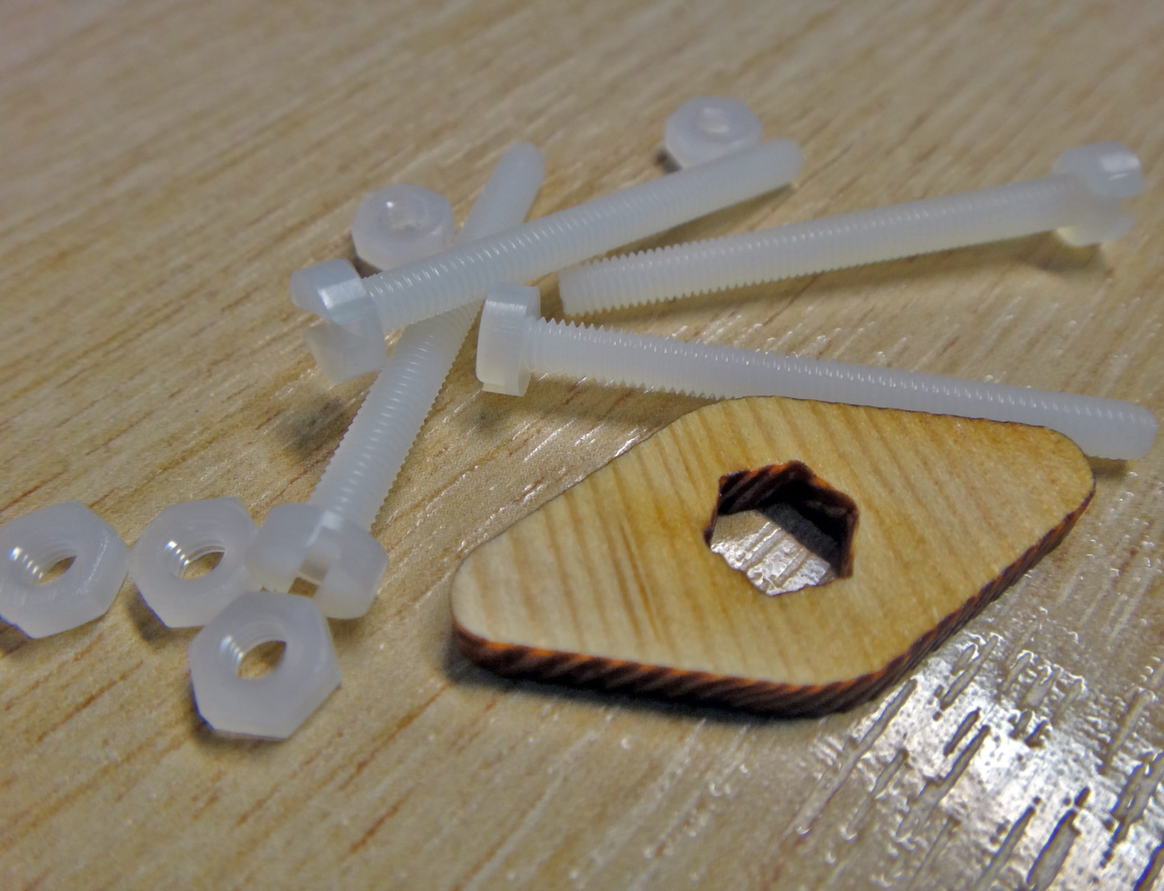
Both the Timber and plastic PiBow cases use 4 nylon bolts. The nuts for these are a little small and fiddley, but you'll find spares in the packet and will get a little laser-cut tool for tightening them.
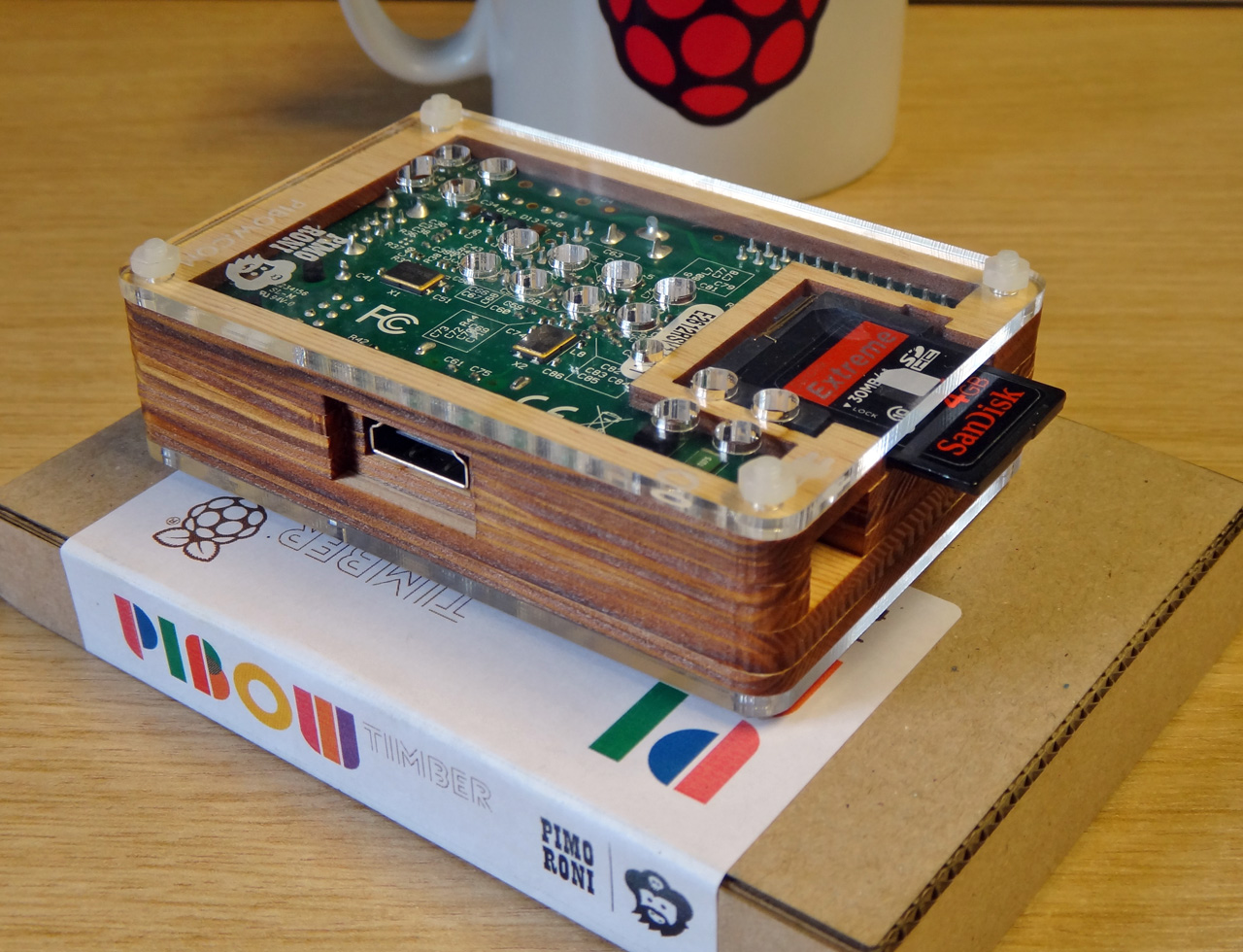
That is until the PiBow Timber. And the only reason it's as good as a PiBow is because it is a PiBow.
The Timber takes the tried and tested PiBow template and applies it to the classic medium of wood. Spruce in this case. The grain and texture of the thin, laser-cut, spruce layers which make up an assembled PiBow Timber lend it an utterly different look and feel to the plastic PiBow. It feels like a traditional piece of computing hardware, or an old Ferguson TV, and looks fantastic as a result.
While I don't want to sound weird. The PiBow Timber also smells utterly fantastic. It's rather like oak smoked salmon, or some other expensive smoked delecacy, and in a very, very good way too. Suffice to say, I have become quite addicted to huffing the rich, smokey aroma of the PiBow Timber... okay, I just got weird.
Although such escapades seem to nausate @pimoroni I'm also a huge fan of combining the PiBow Timber with the classic PiBow rainbow. The 7 layers of the Pi make for an aesthetically pleasing split between two colours, so I decided to mix the Timber with the Rainbow and ended up with a pair of colourful yet understated cases that, once again, evoke those retro computing feelings that, as someone who didn't even live through that era, I shouldn't even be feeling.
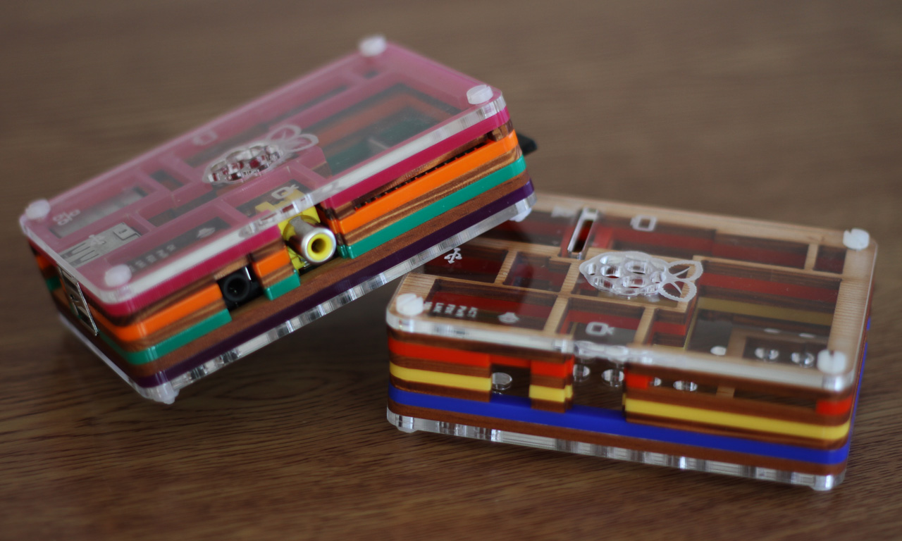
The blend leaves one PiBow with Pink, Orange, Green and Purple layers separated by 3 wooden layers, and another with Blue, Yellow and Red separated by 4 wooden layers. I'm more a fan of the Pink, Orange, Green and Purple combo and will almost certainly be keeping my PiBow assembled this way for a distinctive look.


