Programming Your Pico PiDuino
If you haven't read my guide to assembling your very own ultra-minimalist Breadboard Arduino specifically for your Raspberry Pi, or created your own variant, then you should give it a whirl. The Pico PiDuino is the cheapest way to dip your toes into Arduino-compatible tinkering on your Pi, and needs nothing more than your Pi and a few jump leads to program and talk to it.
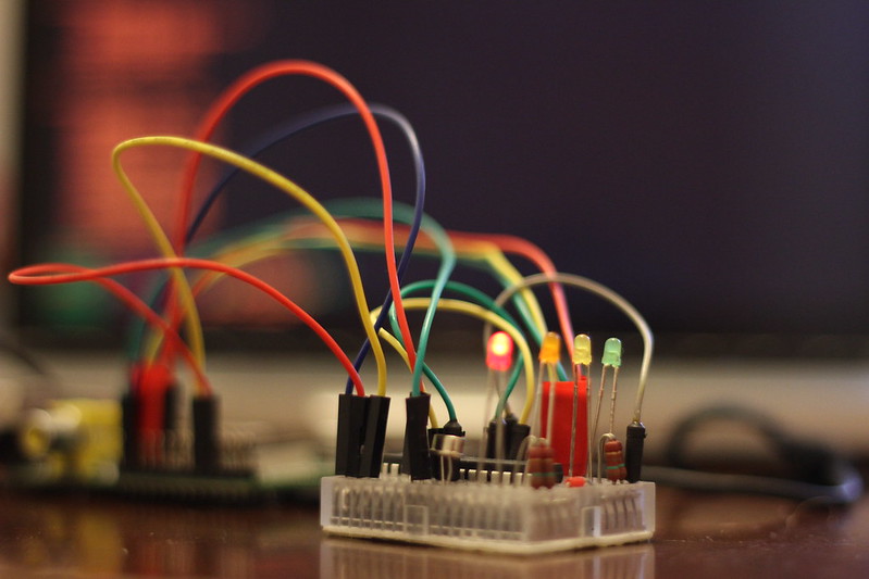
Once again, I recommend this kit from Phenoptix which, if you're in the UK, will cost you £5 and not a penny more. It's what I built my Pico PiDuino with, and it's what inspired this series of tutorials in the first place!
What's covered in this article
This article will cover installing Gordon Henderson's modified AVRdude, which you'll need to flash compiled programs to your Pico PiDuino. If you're feeling brave or using a Beaglebone Black then you can also compile a modified AVRdude from source which includes a Linux SPI programming mode, and a customisable reset pin ( https://github.com/kcuzner/avrdude ).
I will also cover talking to your Pi over Serial, using jump-leads to the Pi's TX/RX. Gordon has a great little setup script to get Serial up and running, and a config file for Minicom, too. I'll also tell you how to set up your /dev/ttyAMA0 to accept echoed strings and transmit them to your PiDuino- this is easy to use in many situations, and means you don't need to worry about a Python or Ruby library just yet (I'll cover using those in a future article).
Once communication is set up, we'll look at using Arduino-mk and the Arduino IDE. I'll be focussing on writing, flashing and compiling code from the command-line using makefiles because the Arduino IDE can be a little sluggish on the Pi, and even more so if you're running headless and trying to use X forwarding. Don't worry, it's easier than it sounds.
A word on vi/vim, the text editor
I tend to use vim to edit files. Most other guides refer you to nano, but I don't use it. To install vim ( VI iMproved ) use: sudo apt-get install vim
Once installed, you can use vim to edit text files, but you'll have to get your head around the Arcane commands used in the editor first.
To go into insert mode, press "i" - you can now type content into your file. There are other ways to go into insert mode, with varying effects, for example "o" will insert a new line.
Also useful to know is that hitting "u" will undo.
If any of these commands result in text appearing in your file, you need to exit edit mode and try again.
To exit insert mode, press "esc"
To save and quit, type ":wq" ( write and quit ) when you're not in edit mode
To quit without saving, type ":q"
Installing AVRdude
The first step is to install AVRdude. AVRdude is the application which will talk to your ATmega and flash your compiled programs to it. I touched upon this in my previous article, so skip ahead if you need to.
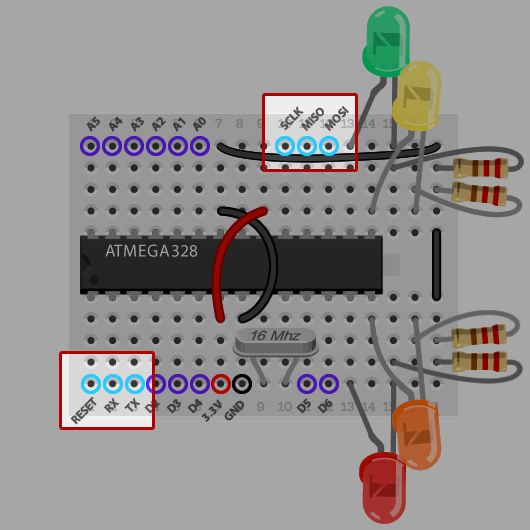
Before starting, make sure your Pico PiDuino is connected properly, you'll need male-to-female jump wires for Reset, MOSI, MISO and CLK. Make sure your power is connected too! For help, check out the Connection Overlay on my assembly microsite and the relevant pins on my Pinout Microsite.
On Raspbian you can install Gordon's AVRdude using the following commands:
cd /tmp
wget https://project-downloads.drogon.net/gertboard/avrdude_5.10-4_armhf.deb
sudo dpkg -i avrdude_5.10-4_armhf.deb
sudo chmod 4755 /usr/bin/avrdude
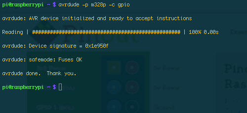
Once done, cross your fingers and verify connectivity with:
avrdude -p m328p -c gpio
Assuming everything is good, and you get a positive response from avrdude which should look something like the below, we can move on to programming.
Programming your Pico PiDuino
Now we're getting to the fun part; making your Pico PiDuino do something meaningful. If you've got 4 LEDs connected as described in my first article this means putting together a simple program to turn them on and off via Serial using the QWER and ASDF keys on your keyboard. It sounds dull, and in the grand scheme of things it is quite dull, but the basics of toggling outputs on your Microcontroller, and responding to Serial commands will help you build more interesting Pico PiDuino projects and work with more exciting hardware.
First thing's first, you need the Arduino IDE and the command-line Arduino Makefile helper installed on your Pi:
sudo apt-get install arduino arduino-mk
Next, make yourself a directory to work in:
mkdir ~/piduino
cd ~/piduino
And create a makefile by saving the following into file entitled "Makefile"
ARDUINO_DIR = /usr/share/arduino
BOARD_TAG = uno
ARDUINO_PORT = /dev/ttyAMA0
ARDUINO_LIBS =
include /usr/share/arduino/Arduino.mk
Now you're going to need something to compile. Although we're working from the command-line, we're still working with the same language you would use in the Arduino IDE; so all the tutorials are applicable. Remember, however, that we don't have an LED connected to Pin 13, but 7, 8, 9 and 10, so adjust any examples you use accordingly.

I've put together this simple variation on Blink which turns on each LED in sequence, and then turns them all off at once. If you're new to Arduino, the below code will introduce you to a few basic concepts. If you're not, just skip to the code!
Arduino basics
The "#define LED_RED 7" allows you to define an unchanging value, which you can reference later. This is useful for assigning friendly names to obscure things like Pin assignments. So we create one constant for each pin.
The "void setup()" function is run when the ATmega first starts up, and is used for setup. "void loop()" is run as fast as the ATmega can run it, and it's where we put things that need to happen repeatedly.
pinMode sets the mode of a pin, pins can be either outputs or inputs- we want OUTPUTs to drive the LEDs and so they're all set as such.
digitalWrite writes a digital value ( either 1, or 0 a.k.a. HIGH or LOW ) to a pin. 1/HIGH means an LED will turn on, and 0/LOW means it will turn off.
delay does just that, delaying the ATmega for a given number of milliseconds.
The code
Save this as “blink.ino” ( or wget https://pi.gadgetoid.com/piduino/blink.ino ) in your piduino folder alongside the Makefile. To compile it, you simply type “make” and wait… and wait. Compiling on the Pi takes a while, even for the simplest of Sketches; I'll have to look into omitting some of the unnecessary libraries.#define LED_RED 7
#define LED_ORANGE 8
#define LED_YELLOW 9
#define LED_GREEN 10
void setup(){
Serial.begin(9600);
//Set all the pins we need to output pins
pinMode(LED_RED, OUTPUT);
pinMode(LED_ORANGE, OUTPUT);
pinMode(LED_YELLOW, OUTPUT);
pinMode(LED_GREEN, OUTPUT);
}
void loop (){
digitalWrite(LED_RED, HIGH);
delay(100);
digitalWrite(LED_ORANGE, HIGH);
delay(100);
digitalWrite(LED_YELLOW, HIGH);
delay(100);
digitalWrite(LED_GREEN, HIGH);
delay(100);
digitalWrite(LED_RED, LOW);
digitalWrite(LED_ORANGE, LOW);
digitalWrite(LED_YELLOW, LOW);
digitalWrite(LED_GREEN, LOW);
delay(100);
}
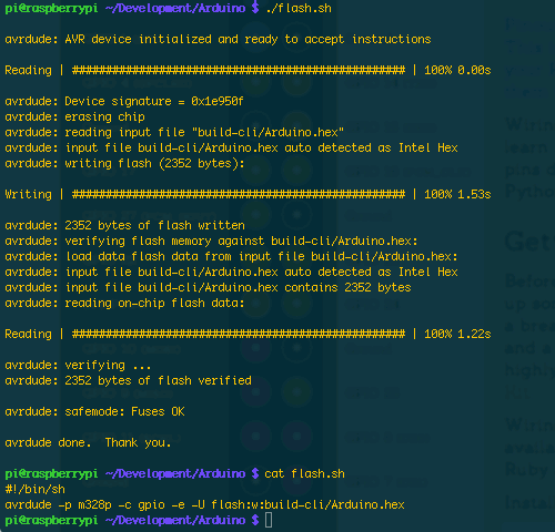
Once compiled, flash with:
avrdude -p m328p -c gpio -e -U flash:w:build-cli/Arduino.hex
I like to put this into a flash.sh file, so flashing is as simple as “./flash.sh”
Note: I've discovered that the .hex file wont always be named "Arduino/hex", use the code below to create your flash.sh to make it easy/generic:
#!/bin/sh
cat build-cli/*.hex > flashme.hex
avrdude -p m328p -c gpio -e -U flash:w:flashme.hex
The result of your flash should look something like this:
Making the ATmega blink a few LEDs is a good learning example, but it's not really useful and doesn't exploit the fact that a 3.3v powered PiDuino can talk directly to your Raspberry Pi over serial. Let's whip up a more complicated example that accepts single-character commands over serial and acts upon them. I'll do the first command - on with q and off with a - and you can try and finish off the code with the rest. Amend your blink.ino file to:
#define LED_RED 7
#define LED_ORANGE 8
#define LED_YELLOW 9
#define LED_GREEN 10

boolean heartbeat = true;

void setup(){
	Serial.begin(9600);

	pinMode(LED_RED,    OUTPUT);
	pinMode(LED_ORANGE, OUTPUT);
	pinMode(LED_YELLOW, OUTPUT);
	pinMode(LED_GREEN,  OUTPUT);
}

void loop (){
	if( heartbeat ){
		digitalWrite(7,HIGH);
		delay(250);
		digitalWrite(7,LOW);
		delay(250);
	}

	if (Serial.available()) {
		heartbeat = false;
		char ser = Serial.read();
		switch (ser) {
			case 'q':
				digitalWrite(LED_Q, HIGH);
				Serial.println("LED 3 ON");
				break;
			case 'a':
				digitalWrite(LED_Q, LOW);
				Serial.println("LED 3 OFF");
				break;
		}
		delay(250);
	}
}
And then “make clean && make” to recompile your sketch before using your flash.sh to flash, or running “avrdude -p m328p -c gpio -e -U flash:w:build-cli/Arduino.hex”
Talking to your Pico PiDuino over serial
Once you’ve got this sketch uploaded, you should notice the Red LED blinking rapidly. I put this “Heartbeat” into the code so you could tell it had flashed successfully. Once the ATmega recieves a command the Heartbeat will stop and you should be able to toggle the LED manually with “q” for on and “a” for off.
You can do this either with Minicom or by echoing these letters to /dev/ttyAMA0 after some setup.
Setting up Minicom
Once again we refer to the almighty Gordon for Minicom setup.
As per his instructions, first you should install Minicom
sudo apt-get install minicom
Then go into the minicom config dir:
cd /etc/minicom
And create a new config file:
sudo vi minirc.ama0
And paste in the settings ( don't forget to press "i" first if you're using vi/vim ):
pu port             /dev/ttyAMA0
pu baudrate         9600
pu bits             8
pu parity           N
pu stopbits         1
pu minit
pu mreset
pu rtscts           No
Once set up, simply type:
minicom ama0
And you'll be greeted with a terminal. Now you should be able to press "q" to turn the Red LED on, and "a" to turn it off again.
Using /dev/ttyAMA0
Minicom does the trick, but what if you want to send a string of commands and have your Piduino intepret them one at a time?
You can do this with a simple one-liner:
stty -F /dev/ttyAMA0 speed 9600 cs8 -cstopb -parenb
Then you can just:
echo "qaqaqaqa" > /dev/ttyAMA0
Which should turn the Red LED on and then off again 4 times.
Stay Tuned!
I've had success programming a Pico PiDuino with the BeagleBone Black, although the setup is a little trickier, it requires Ubuntu for starters, and the pinout is a little confusing due to the Bone's many, many GPIO pins. Still, I have a guide in the works for Beaglebone Black users, so stay tuned!
I have a couple of ideas in mind for the next article in the series. Let me know via Twitter @gadgetoid which you prefer. Either committing the Pico PiDuino to perfboard, or getting some more exciting components connected.
Useful Links
- https://pi.gadgetoid.com/pinout/atmega328-arduino Raspberry Pi to ATmega 328 programming pinout
- https://pi.gadgetoid.com/piduino/pico-piduino - Pico PiDuino Assembly Guide
- https://projects.drogon.net/raspberry-pi/gertboard/arduino-ide-installation-isp/ - Arduino IDE/modified AVRdude installation
- https://www.phenoptix.com/products/bare-bones-breadboard-arduino… - Barebones Arduino-compatible kit from Phenoptix
« Back to index Posted on 2013-09-15 by Philip Howard