Pi GPIO Breakout Board and Port Expander Kits
Although I may not have posted an update for a while, I've still kept myself abreast of the Pi and the various recent developments, and I'm still waiting for my second, hopefully Welsh manufactured, Pi to arrive. This will allow me a little more opportunity to hack around without disturbing this blog, which has now been hosted uninterrupted for 100 days on my Raspberry Pi.
I've been keeping my eye on HobbyTronics, too, and as soon as they got the ST7565 Negative LCD in stock, I ordered it with a couple of their shiny new Pi accessories; the Raspberry Pi GPIO Breakout Board Kit and the Raspberry Pi MCP23017 Port Expander Board Kit.
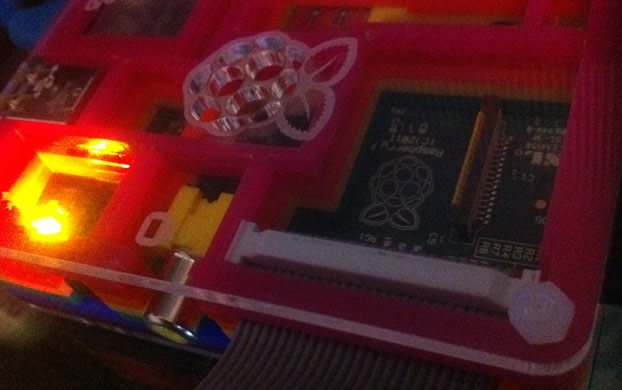
Yesterday I soldered up the Pi GPIO breakout board and IO expansion board, and this morning I removed the SKPang case from my Pi, which doesn't fit a ribbon cable particularly well, and built the PiBow up around my running Pi. So, let's tackle these various different additions to my Pi armoury in no particular order.
A small mod with wire cutters let the ribbon cable pass unhindered
First up, the PiBow. Is an attractive and cleverly engineered case which fits my Pi like a glove. It was easy enough to assemble around the running Pi, and the multi-layered construction makes for a very durable and very attractive case for toting the Pi around in a bag. Where it fell short, however, was the cut out for a GPIO ribbon cable. My cable either had atypically large connectors on the ends, or wasn't flexible enough, but I had to take the layer of the PiBow with a little groove for the ribbon cable and snip out a portion of the plastic. Ultimately, though, it was easy to do, and didn't ruin the look of the PiBow so it's not a huge complaint.
The PiBow is good enough that I'm considering picking up a second one for my second Pi, I haven't yet seen another case that I particularly like yet. The PiBow really shows up the grey ribbon cable though, so I'm going to cave in and find a rainbow alternative.
Next up, the HobbyTronics GPIO breakout board. Its a simple piece of kit which adapts the ribbon connection to a breadboard-friendly set of headers. Unlike the basic Adafruit Pi Cobbler, however, the HobbyTronics board includes an additional header which breaks out power, data and clock lines onto which the Port Expander board can be connected.
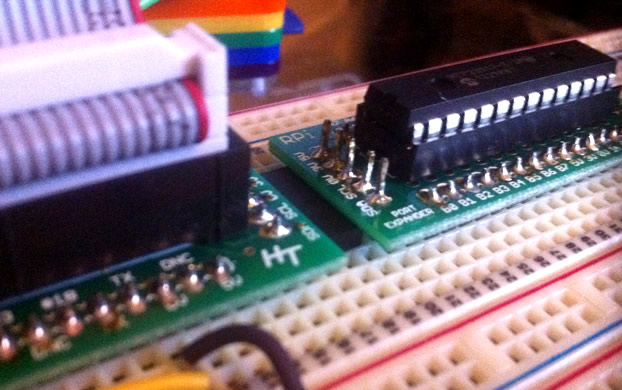
I soldered the headers underneath to keep things tidy and avoid needing to trim the pins
The expansion board is i2c and can be daisy-chained to provide more IO than you could possibly know what to do with. It also includes a socket, so you can pop the MCP23017 chip out and use it on a breadboard if you're so inclined.
I was baffled by the fact that the included male and female headers didn't line up when placed on the port expander and GPIO breakout, but a quick look at the HobbyTronics website suggests pulling the male pins out of their plastic support and soldering them on individually. I did this, and plugged the pins into the female header while soldering to keep them lined up. I also soldered the headers underneath the boards, both because I think it looks better, and leaves the pin labels visible for future hackery.
I also found that soldering them on top would cause problems with the abnormally long male pins touching the breadboard when the boards are inserted all the way.
The GPIO breakout and port expander eat up a lot of room, so a 830 point breadboard is about the minimum you can get away with, without connecting the two with jump leads.
With the low price and fairly simple construction ( any surface mount components are already soldered on ) these boards are an excellent and good value addition to your Pi. Just be wary that the GPIO breakout board does not include any additional protection for your Pi's GPIO pins. I'm pretty terrible at soldering, but still managed to assemble both quickly. Using a piece of old strip-board to align the headers made it easy, just pop the headers into the strip-board and pop the board on top to solder. You can also use breadboard for this, but I don't trust myself with plastic around a soldering iron!
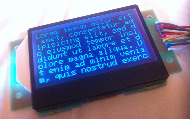
It may not look it, but to the eye this screen is beautifully crisp and readible from a fair distance
The ST7565 LCD is something I've been waiting to get my hands upon for a while. The negative model in particular works beautifully with the RGB backlight and can quite easily be adjusted to a super black positive LCD by inverting the contents of the buffer before sending it to the screen ( you can do this easily by subtracting each byte from 255 ). Its actually quite a lot more readable when inverted.
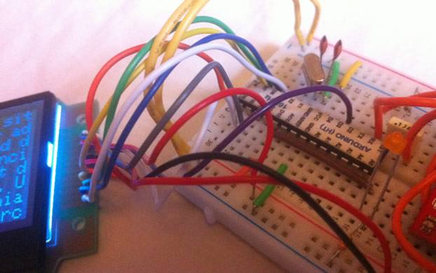
Gratuitous wiring joins the Arduino and ST7565, but plenty of IO remains
Unfortunately the RGB backlight makes it very hard to achieve a consistent brightness when fading between colours, and it also requires PWM which I wouldn't entrust the Pi to provide directly. Fortunately the Arduino is a dab hand at things like this, and I will use one of my breadboard ATMega chips as a smart PWM driver, accepting colours over serial and handling the transition between whatever colour is currently displayed and the new one requested.
Ultimately the Arduino is a brilliant stand-in for various IO expanders, handling ADC, PWM and digital IO with ease and lending a bit of intelligence, stability and autonomy to these processes.
« Back to index Posted on 2012-10-14 by Philip Howard