Building the Pico PiDuino - A cheap barebones Arduino compatible for your Pi
There's little doubt that you've at least heard of Arduino if you're interested in hacking around with hardware on the Raspberry Pi.
Arduino have brought a whole variety of Atmel-based boards to the market, coupled with the easy to use Arduino IDE, in an effort to let hardware hackers, hobbyists and professional prototypers easily get up and running with Microprocessor development. Unfortunately, the official Arduino boards can be a little pricy if you're just wanting to dip your toes into the Arduino/Microprocess programming water.
The good news is that all you really need is an Atmel ATmega processor, a handful of components and a Raspberry Pi. You can pick all this up ( apart from the Pi ) for little over a fiver.
I should probably start with a disclaimer; the Arduino-compatible we're going to build in this tutorial is absolutely, totally, irresponsibly barebones. In a proper breadboard Arduino build you should have a host of capacitors to decouple your power supply, and probably at least some protection circuitry between it and your Pi. If you're at all concerned about blowing up your Pi, read no further!
Introducing the Pico PiDuino
This is the first in a series of guides detailing how to build and program an ATmega 328-based Arduino-compatible microcontroller using only your Raspberry Pi.
First, I'll will walk you through obtaining the parts and assembling what I will refer to henceforth as the Pico PiDuino.
The next guide in this series will teach you how to program it, and then talk to it over serial from the Pi.
The Pico PiDuino is a barebones Arduino-compatible, that means it works with the Arduino IDE and uses the Arduino bootloader. It's designed specifically to be connected to, and powered by the Pi - but you can program it with a USB-to-Serial breakout or power it standalone with a handful of batteries or even, with the right components, a mains adaptor.
Why learn to program an ATmega/Arduino?
Because of their flexibility and robustness, being able to program a microcontroller is a useful and rewarding skill to have, and it's fortunate that it's possible to leverage your Pi to get started quickly and cheaply with a trusty ATmega 328.
- Learning to program an ATmega, or Arduino, will allow you to build much more specialist control systems which use less power, are much less complex, less prone to failure and more robust than the Pi. These are great for things that the Pi isn't necessary for.
- Once you've grasped the basics and have a project in mind, you can even move on to playing with some of the brilliant official Arduino boards and all the programming skills you pick up will translate right over.
- If you're wanting to produce your own product for sale, you can build your own hardware around an Arduino-compatible ATmega, program your software in the IDE and ship a finished design supporting an ATmega 328p or similar microprocessor.
- It's a fun challenge for a weekend.
The bill of materials
If you're still with me, then I'm going to assume you've got a reckless and irresponsible streak and want to hook an ATmega directly to your Pi and get started as fast and cheap as possible. Enough introduction; Let's get started!
You will need:
- One ATmega 328p Microproccessor, in a 28-pin, breadboard-friendly package
- One 16Mhz Crystal Oscillator
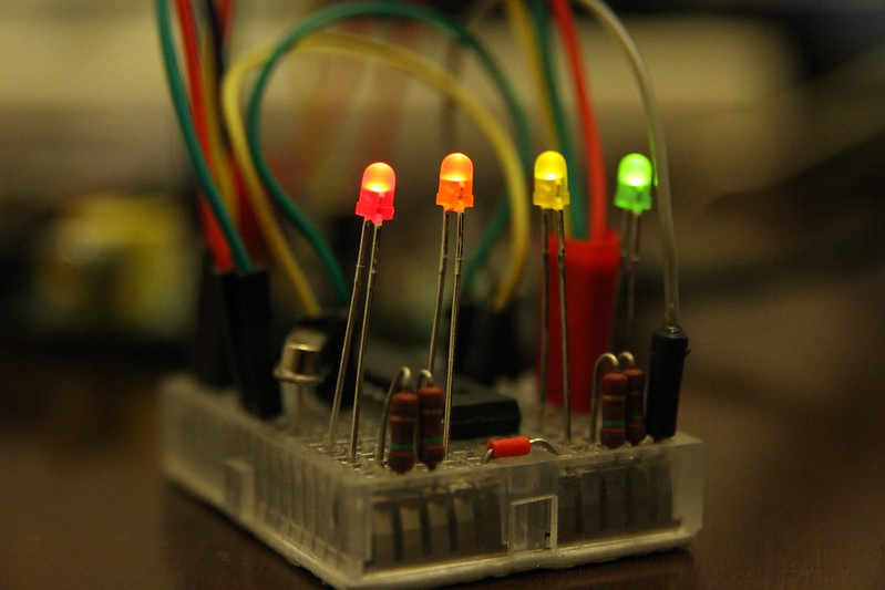
- 4 LEDs, it doesn't matter what colour but Red, Orange, Yellow and Green look nice together
- 4 resistors for your LEDs, about 220 Ohm or higher
- 8 female-to-male jump wires for connecting your Pi to the Breadboard Arduino-compatible
- 4 male-to-male jump wires for wiring up the Breadboard Arduino-compatible ( or 3 jump wires and a 0Ohm resistor )
- And to build it on: One 170 point breadboard, the really, really tiny one
To avoid confusion, I recommend using Red and Black wires for your Live and Ground connections and picking 8 other distinct colours, if you can, for the other connections. Connecting leads in the wrong place can have "undesired" results. To be extra-safe you should always shut down your Pi before connecting jump leads, but I'll let you in on a secret; I don't!
The best way to get most of the parts you need is the fantastically good value "Bare Bones" £5 Arduino Kit from Phenoptix. In fact that's the very kit I'm working with. It also comes with a host of protective capacitors, a reset switch and some other components for a stand-alone Arduino that you wont need for this tutorial. If you don't have jump wires then you can also pick up a pack of M/F jump wires, far more than you'll need! If you go for this kit, you'll also need to dig up 3 more LEDs ( or 4 of any type ) and 3 or 4 resistors to go with them.
Putting it together
What we're effectively building is an even more minimal version of the "Shrimp" variety of Arduino-compatible, with 4 LEDs for you to experiment with. We won't be using capacitors on the crystal (unless you feel you need to), or the reset capacitor or pull-up resistor; it's quicker and easier to omit these until you need to use your mini Arduino for something other than tinkering. In my experience, my Pi didn't agree with having a pull-up resistor on the reset line and trashed its SD card twice; this hasn't happened since I removed it. It could be coincidence, but I'm not taking any chances.
To make things really easy, I've built a micro-site which will walk you through the build process. Find it here: https://pi.gadgetoid.com/piduino/pico-piduino
We'll be aligning the ATmega to the left of the breadboard and using the space at the other end to squeeze in the LEDs.
- Orientate your Breadboard so that the number 1 ( numbers should be visible faintly on the edge ) is at the bottom left
- Place your ATmega with the little notch facing left, and aligned against the left edge of the Breadboard
- Make sure the ATmega pins line up with the holes on the breadboard, and push it firmly in with even pressure.
- Locate column 9 and 10 on the bottom edge ( with the notch facing left ), and bridge them with the Crystal Oscillator. If you can't see numbers, count the holes.
- Grab one male to male jump wire, preferably a red one, and bridge column 7 on the bottom edge to column 9 on the top edge
- Grab another male to male jump wire, preferably a black one, and bridge column 8 on the bottom edge to column 7 on the top edge
- Grab the next jump wire, or an 0 Ohm resistor, and connect the lower column 17 to the upper one, creating a mini Ground rail for your LEDs
- Grab your last jump wire and bridge the top of column 17 to the top of column 7 to ground your LEDs Ground rail
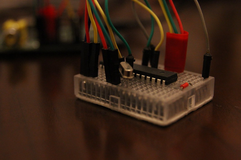
You now have a working ATmega on a breadboard. Yes, it's that simple to get started! If you're confident getting it hooked up you can now visit my Pico Piduino assembly micro-site and click "Connection Overlay" to see where things should connect.
Cross reference this with my Piout Microsite to see which pins on the Pi are the ones you need to connect it to.
To verify that your ATmega is set up correctly and can be programmed, you need to set up the programming connections which are as follows:
- Connect Reset on your Pico PiDuino to GPIO 8 on the Pi
- Connect MOSI to GPIO 10/MOSI on the Pi
- Connect MISO to GPIO 9/MISO on the Pi
- Connect SCLK to GPIO 11/SCLK on the Pi
Finally, connect the end of column 7 on your Pico PiDuino to your Pi 3.3v Pin, I recommend using pin 17 and the end of column 8 to the Ground on your Pi. I use pin 25 at the bottom right. This should keep all your connections in one tidy block.
Testing your Pico PiDuino
First you'll need to install Gordon's modified Avrdude on Raspbian, that means doing the following:
cd /tmp
wget https://project-downloads.drogon.net/gertboard/avrdude_5.10-4_armhf.deb
sudo dpkg -i avrdude_5.10-4_armhf.deb
sudo chmod 4755 /usr/bin/avrdude
Once installed, you can check your Pico PiDuino is set up and connected correctly using:
avrdude -p m328p -c gpio
If everything is working fine you should see something like: "avrdude: AVR device initialized and ready to accept instructions" If so, well done! Let's add some LEDs.
If not, double check your connections. It should help to follow my assembly guide and use the Connection Overlay.
Adding the LEDs
If you haven't already jumped the gun, you'll notice that I didn't connect the LEDs above. It helps to do things in phases, and once we've got a working ATmega up and running it makes sense to test it.
The LEDs are cleverly clustered around the Arduino digital pins 7, 8, 9 and 10. These are good for a number of reasons:
- They're right at the end of the ATmega
- They're in sequence
- They don't conflict with any of the programming functionality
Most normal Arduino builds assume pin 13 is an LED, so if you use any demos from the Arduino website, or for any other Arduino-compatible devices make sure you update the LED pin to 7, 8, 9 or 10.
Connect the LEDs and resistors as follows:
- Put the long leg of the Red LED into column 13 at the very bottom, and the short leg into column 15
- Put the long leg of the Orange LED into column 14 right up against the ATmega, and the short leg into column 16
- Put the long leg of the Yellow LED into column 14 on the top half of the breadboard, again right up against the ATmega, and the short leg into column 16
- Put the long leg of the Green LED into column 13 at the very top of the breadboard, and the short leg into column 15
By now you should have 4 LEDs connected in two pairs, with two rows gap between them. Place a resistor in each of these 4 rows, bridging the short leg of each LED to the Ground rail.
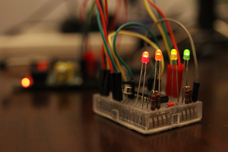
We're done. Make sure everything is connected properly and fire up avrdude for one last test:
avrdude -p m328p -c gpio
Successful? Well, I'm afraid this article is getting a little long and I'll have to end here. Stay tuned for the next in the series when we will learn how to program your ATmega-powered Pico PiDuino from the command-line.
Useful links
- https://pi.gadgetoid.com/pinout/atmega328-arduino Raspberry Pi to ATmega 328 programming pinout
- https://pi.gadgetoid.com/piduino/pico-piduino - Pico PiDuino Assembly Guide
- https://projects.drogon.net/raspberry-pi/gertboard/arduino-ide-installation-isp/ - Arduino IDE/modified AVRdude installation
- https://www.phenoptix.com/products/bare-bones-breadboard-arduino… - Barebones Arduino-compatible kit from Phenoptix
« Back to index Posted on 2013-09-15 by Philip Howard